Shunze 學園 >資訊設備專區 >Extreme & Enterasys > 《分享》VRRP架構 哈囉,還沒有註冊或者登入。請你[註冊|登入]
« 上一篇主題 下一篇主題 » 顯示成列印模式 | 增加到我的最愛
發表新主題 發表回覆
作者
主題
shunze
工友伯伯


註冊日期: 2002 04
來自: 潮汐終止之地
文章: 2380

shunze 離線
《分享》VRRP架構引用回覆 編輯/刪除文章 搜尋由  發表的其他文章 回報給版主 IP 位置 回此頁最上方

*VRRP is available on platforms with an Advanced Edge or Core license.

VRRP: Virtual Router Redundancy Protocol

VRRP是一種路由備援協議,多台router間以一個虛擬IP做為提供服務的路由IP。
同一時間只會有一台router做為Master角色,對應到此虛擬IP負責轉發數據封包,而其它router則為Backup角色。
一旦Master router故障不可用,VRRP會以動態的轉移機制,將Master的角色移轉到其它Backup router,
讓環境中路由不致停擺,持續維持可用狀態。
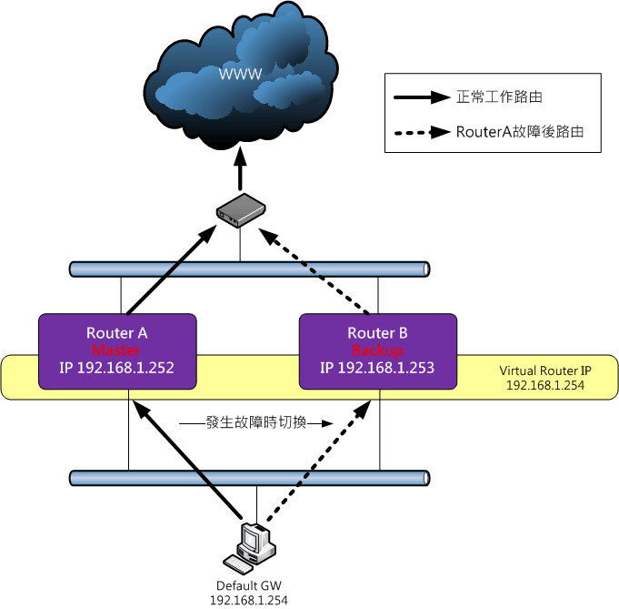


VRRP的設定要點如下

  • 建立VRRP instance。
    create vrrp vlan <VLAN-Name> vrid <VRRP-ID>

    VRRP-ID最多支援 7 組,不同的VLAN可使用相同的VRRP-ID,最多可建立 128 組instance。

  • 設定該instance所提供服務的virtual router IP位址。
    configure vrrp vlan <VLAN-Name> vrid <VRRP-ID> add <VRRP-IPAddress>

    該virtual router IP的MAC address為00-00-5E-00-02-<VRRP-ID>

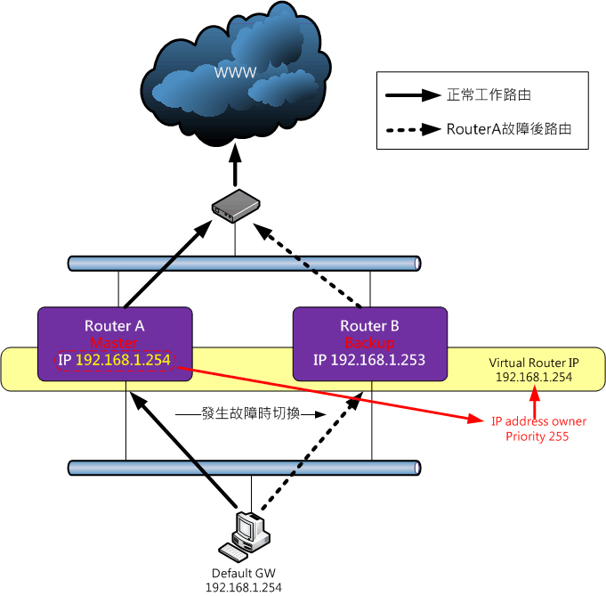
    若virtual router IP設定為跟某router IP相同,
    則此router為IP address owner router,擁有最高的優先權 255,直接做為Master Router。

  • 設定宣傳的間隔時間。
    configure vrrp vlan <VLAN-Name> vrid <VRRP-ID> advertisement-interval <Number> seconds

    VRRP透過multicast來進行advertisement,multicast IP位址是 224.0.0.18(IPv4) 與 ff02::12(IPv6)。
    Advertisement-interval預設為 1 秒,V3版最長時間為40秒。
    VRRP成員的宣傳時間設定需一致,若兩著不同,Master的宣傳時間會套用到Backup Router上。

  • Router的優先權設定。
    configure vrrp vlan <VLAN-Name> vrid <VRRP-ID> priority <Number>

    Priority數字愈大優先權愈高,最大值是 255,預設為 100,可設定值是1-254。
    255 保留給IP Owner Address Router使用,
    0 保留給Master Router,做為宣告放棄Master角色時所使用。

    設定時,可將Master Router的優先權設定為大於100的數字;而Backup則因預設值為100,所以可以不用再設定,即產生Master/Backup的優先順序差異。

  • 設定套用的VRRP版本。
    configure vrrp vlan <VLAN-Name> vrid <VRRP-ID> version [v3-v2 | v3 | v2]

    XOS的VRRP版本預設為 v2

  • Preemption,Master role搶奪設定。
    Preemption的功能是允許擁有較高優先權的Backup Router,搶奪走Master的角色。
    configure vrrp vlan <VLAN-Name> vrid <VRRP-ID> preempt delay <Number>

    當時間設定在 13600 之間時,若有較低優先權的Master Router存在,一旦超過設定時間,較高優先權的Backup Router,會搶走Master的角色。
    預設值為 0,若設定為 0,則在三次advertisement time後,較高優先權的Backup Router,會搶走Master的角色。

  • 設定VRRP的驗證模式。
    configure vrrp vlan <VLAN-Name> vrid <VRRP-ID> authentication [none | simplepassword <Your-Password>]

    預設值為 none。因V3版已廢棄驗證功能,故建議設定為none,不要套用驗證模式。

  • 設定Track-mode。
    configure vrrp vlan <VLAN-Name> vrid <VRRP-ID> track-mode [all | any]

    Track-mode是用來測試Router對外的連結能力,進而判斷該Router是否還適合當Master Router,預設為all。
    Tracking的方法有三種,VLAN、Route Table與ping。
    1. VLAN Tracking可設定監測8組VLAN
      configure vrrp vlan <VLAN-Name> vrid <VRRP-ID> add track-vlan <target_vlan_name>
      configure vrrp vlan <VLAN-Name> vrid <VRRP-ID> delete track-vlan <target_vlan_name>

    2. Route Table Tracking可指定多組路由表做為監測
      configure vrrp vlan <VLAN-Name> vrid <VRRP-ID> add track-iproute <ipaddress/masklength>
      configure vrrp vlan <VLAN-Name> vrid <VRRP-ID> delete track-iproute <ipaddress/masklength>

    3. Ping Tracking則是可指定多組IP以ping做為監測
      configure vrrp vlan <VLAN-Name> vrid <VRRP-ID> add track-ping <ipaddress> frequency <seconds> miss <misses>
      configure vrrp vlan <VLAN-Name> vrid <VRRP-ID> delete track-ping <ipaddress> frequency <seconds> miss <misses>

    採用 all 時,是上述三種方式中,有一種全部failed,才判斷為失去對外連結能力;
    而採用 any 時,則是上述三種方式中,有任何一個failed,即判斷為失去對外連結能力。

  • 設定Accept-mode。
    configure vrrp vlan <VLAN-Name> vrid <VRRP-ID> accept-mode [on | off]

    是否讓Switch處理目的地為虛擬router IP的non-ping封包,預設值為 off
    只有當要把virutal router IP做為NTP Server位址時才要設為on,否則請設為off。

  • 啟用該VRRP instance。
    enable vrrp {vlan <VLAN-Name> vrid <VRRP-ID>}


查看VRRP的相關指令如下。
show vrrp {detail}
show vrrp vlan <VLAN-Name> {stats}


♥順子老婆的網拍,請多關照∼

If you don't like something, change it.
If you can't change it, change your attitude.
Don't complain!


2015-08-20, 18:41 shunze 的個人資料 把 shunze 加入好友列表 發送Email給 shunze 瀏覽 shunze 的網站 MSN : shunze@gmail.com
shunze
工友伯伯


註冊日期: 2002 04
來自: 潮汐終止之地
文章: 2380

shunze 離線
《分享》VRRP範例練習引用回覆 編輯/刪除文章 搜尋由  發表的其他文章 回報給版主 IP 位置 回此頁最上方

示範環境

  • 兩台Router分別建立三個VLAN;V10,V20與V30。
    V10為192.168.1.0/24網段
    V20為192.168.2.0/24網段
    V30為192.168.3.0/24網段
  • Port 1-10為V10,Port 11-20為V20,Port 24為V30。
  • Default route為192.168.3.1
  • RouterA為Master Router,RouterB為Backup Router


VRRP設定
  1. 建立VLAN
    RouterA
    configure vlan default delete ports all
    create vlan V10
    configure vlan V10 tag 10
    configure vlan V10 add ports 1-10
    configure vlan V10 ipaddress 192.168.1.252/24

    create vlan V20
    configure vlan V20 tag 20
    configure vlan V20 add ports 11-20
    configure vlan V20 paddress 192.168.2.252/24

    create vlan V30
    configure vlan V30 tag 30
    configure vlan V30 add ports 24
    configure vlan V30 ipaddress 192.168.3.252/24

    RouterB
    configure vlan default delete ports all
    create vlan V10
    configure vlan V10 tag 10
    configure vlan V10 add ports 1-10
    configure vlan V10 ipaddress 192.168.1.253/24

    create vlan V20
    configure vlan V20 tag 20
    configure vlan V20 add ports 11-20
    configure vlan V20 paddress 192.168.2.253/24

    create vlan V30
    configure vlan V30 tag 30
    configure vlan V30 add ports 24
    configure vlan V30 ipaddress 192.168.3.253/24


  2. 啟用Routing
    enable ipforwarding
    configure iproute add default 192.168.3.1

    兩邊router都要啟用routing。

  3. 架設VRRP
    RouterA
    create vrrp vlan V10 vrid 1
    configure vrrp vlan V10 vrid 1 add 192.168.1.254
    configure vrrp vlan V10 vrid 1 priority 150
    enable vrrp vlan V10 vrid 1

    create vrrp vlan V20 vrid 1
    configure vrrp vlan V20 vrid 1 add 192.168.2.254
    configure vrrp vlan V10 vrid 1 priority 150
    enable vrrp vlan V20 vrid 1

    create vrrp vlan V30 vrid 1
    configure vrrp vlan V30 vrid 1 add 192.168.3.254
    configure vrrp vlan V30 vrid 1 priority 150
    enable vrrp vlan V30 vrid 1


    RouterB
    create vrrp vlan V10 vrid 1
    configure vrrp vlan V10 vrid 1 add 192.168.1.254
    enable vrrp vlan V10 vrid 1

    create vrrp vlan V20 vrid 1
    configure vrrp vlan V20 vrid 1 add 192.168.2.254
    enable vrrp vlan V20 vrid 1

    create vrrp vlan V30 vrid 1
    configure vrrp vlan V30 vrid 1 add 192.168.3.254
    enable vrrp vlan V30 vrid 1


狀態查看
show iproute


由routing table來看,路由還是指向router個體。
但由VRRP來看,RouterA的狀態是MSTR,負責VRRP Virtual IP mapping過來的路由工作;
而RouterB的狀態是BKUP,做為備援router用。

show vrrp


♥順子老婆的網拍,請多關照∼

If you don't like something, change it.
If you can't change it, change your attitude.
Don't complain!


2015-08-21, 16:27 shunze 的個人資料 把 shunze 加入好友列表 發送Email給 shunze 瀏覽 shunze 的網站 MSN : shunze@gmail.com
shunze
工友伯伯


註冊日期: 2002 04
來自: 潮汐終止之地
文章: 2380

shunze 離線
《分享》VRRP與MLAG搭配使用引用回覆 編輯/刪除文章 搜尋由  發表的其他文章 回報給版主 IP 位置 回此頁最上方

在中、大型環境,採用chassis switch無法進行堆疊的架構時,
為了保持路由與線路的redundancy,大多都會採用VRRP與MLAG併用,
以確保其中任一chassis switch故障時,不會對網路環境產生影響。

示範環境

  • 兩台Router分別建立三個VLAN;V10,V20,V30與ISC。
    V10為192.168.1.0/24網段
    V20為192.168.2.0/24網段
    V30為192.168.3.0/24網段
    ISC為10.0.0.0/30網段,做為MLAG溝通管道
  • Port 1-10為V10,Port 11-20為V20,Port 24為V30,Port 21-22為ISC。
  • Default route為192.168.3.1
  • RouterA為Master Router,RouterB為Backup Router


  1. 建立VLAN
    RouterA
    configure vlan default delete ports all
    create vlan V10
    configure vlan V10 tag 10
    configure vlan V10 add ports 1-10
    configure vlan V10 ipaddress 192.168.1.252/24

    create vlan V20
    configure vlan V20 tag 20
    configure vlan V20 add ports 11-20
    configure vlan V20 paddress 192.168.2.252/24

    create vlan V30
    configure vlan V30 tag 30
    configure vlan V30 add ports 24
    configure vlan V30 ipaddress 192.168.3.252/24

    create vlan ISC
    enable sharing 21 group 21,22 lacp
    configure vlan ISC tag 3000
    configure vlan ISC add ports 21 tag
    configure vlan ISC ipaddress 10.0.0.1/30

    RouterB
    configure vlan default delete ports all
    create vlan V10
    configure vlan V10 tag 10
    configure vlan V10 add ports 1-10
    configure vlan V10 ipaddress 192.168.1.253/24

    create vlan V20
    configure vlan V20 tag 20
    configure vlan V20 add ports 11-20
    configure vlan V20 paddress 192.168.2.253/24

    create vlan V30
    configure vlan V30 tag 30
    configure vlan V30 add ports 24
    configure vlan V30 ipaddress 192.168.3.253/24

    create vlan ISC
    enable sharing 21 group 21,22 lacp
    configure vlan ISC tag 3000
    configure vlan ISC add ports 21 tag
    configure vlan ISC ipaddress 10.0.0.2/30


  2. 啟用Routing
    enable ipforwarding vlan V10
    enable ipforwarding vlan V20
    enable ipforwarding vlan V30
    configure iproute add default 192.168.3.1

    兩邊router都要啟用routing,但ISC vlan不用加入routing。

  3. 設定MLAG Peer
    RouterA
    create mlag peer "RouterB"
    configure mlag peer "RouterB" ipaddress 10.0.0.2

    RouterB
    create mlag peer "RouterA"
    configure mlag peer "RouterA" ipaddress 10.0.0.1


  4. 設定MLAG Port
    RouterA
    enable sharing 1 grouping 1 lacp
    enable mlag port 1 peer "RouterB" id 1

    enable sharing 11 grouping 11 lacp
    enable mlag port 11 peer "RouterB" id 11

    enable sharing 24 grouping 24 lacp
    enable mlag port 24 peer "RouterB" id 24

    RouterB
    enable sharing 1 grouping 1 lacp
    enable mlag port 1 peer "RouterA" id 1

    enable sharing 11 grouping 11 lacp
    enable mlag port 11 peer "RouterA" id 11

    enable sharing 24 grouping 24 lacp
    enable mlag port 24 peer "RouterA" id 24


  5. 增加ISC Port所對應的VLAN TAG
    configure vlan V10 add port 21 tag
    configure vlan V20 add port 21 tag
    configure vlan V30 add port 21 tag

    兩邊Router都要做。

  6. Edge Switch設定LACP與上層MLAG port對接
    enable sharing 1 group 1,2 lacp

    這範例Edge Switch是以第1,2 port組成lacp group,與上層Core Switch的MLAG port對接。
    由於MLAG的部分順子採用lacp,故Edge Switch一樣要用lacp才能對應。

  7. 架設VRRP
    RouterA
    create vrrp vlan V10 vrid 1
    configure vrrp vlan V10 vrid 1 add 192.168.1.254
    configure vrrp vlan V10 vrid 1 priority 150
    enable vrrp vlan V10 vrid 1

    create vrrp vlan V20 vrid 1
    configure vrrp vlan V20 vrid 1 add 192.168.2.254
    configure vrrp vlan V10 vrid 1 priority 150
    enable vrrp vlan V20 vrid 1

    create vrrp vlan V30 vrid 1
    configure vrrp vlan V30 vrid 1 add 192.168.3.254
    configure vrrp vlan V30 vrid 1 priority 150
    enable vrrp vlan V30 vrid 1


    RouterB
    create vrrp vlan V10 vrid 1
    configure vrrp vlan V10 vrid 1 add 192.168.1.254
    enable vrrp vlan V10 vrid 1

    create vrrp vlan V20 vrid 1
    configure vrrp vlan V20 vrid 1 add 192.168.2.254
    enable vrrp vlan V20 vrid 1

    create vrrp vlan V30 vrid 1
    configure vrrp vlan V30 vrid 1 add 192.168.3.254
    enable vrrp vlan V30 vrid 1


Active-Active VRRP

若環境中只有兩台Core Switch,且以VRRP+MLAG進行組態,
那麼在此架構下,是可以做到VRRP的Active-Active模式!
設計概念很簡單,只要在MLAG的ISC通道兩端,把VRRP的advertisement訊息擋掉即可。


由於VRRP的advertisement訊息無法傳達溝通,所以在這樣的情況下,
兩台Switch都會是Master Router的角色,達到了Active-Active的效果!

設定要領
  1. 建立一擋掉advertisement訊息的ACL。
    vi policy vrrp-hello-block

    entry vrrp-block {
        if match all {
            destination-address 224.0.0.18/32 ;
        } then {
            deny ;
        }
    }

  2. 將此ACL套用在ISC的兩端的port上。
    configure access-list vrrp-hello-block port 21 ingress

另外,在設定Active-Active的VRRP時,有一個條件限制要留意,
那就是Virtual Router IP不能是Router介面IP,也就是一開始說的IP address owner router那種形態;
一定要是一個獨立、與兩端IP都不相同的Virtual IP才行。


♥順子老婆的網拍,請多關照∼

If you don't like something, change it.
If you can't change it, change your attitude.
Don't complain!


2015-08-22, 20:57 shunze 的個人資料 把 shunze 加入好友列表 發送Email給 shunze 瀏覽 shunze 的網站 MSN : shunze@gmail.com
  « 上一篇主題 下一篇主題 »
發表新主題 發表回覆
跳到:

Powered by: Burning Board 1.1.1 2001 WoltLab GbR